 Skip to content
Discover the critical role of antenna cables in today’s technology-driven world. Whether you’re setting up a home entertainment system, enhancing your device’s connectivity, or embarking on a technical project, understanding the nuances of antenna cables can make all the difference.
Antenna cables, often overlooked, are the lifelines connecting devices like modems, routers, and phones to antennas via coaxial cables. Their quality directly influences the performance of your antenna, affecting signal strength and clarity.
Let’s dive deeper into the world of antenna cables, uncovering their types, functionality, and importance.
What Type of Cable Is Antenna Cable?
Antenna cables are specifically designed to transmit radio frequency signals from an antenna to a television, radio, or other electronic device. They are commonly used for connecting outdoor antennas to TVs, satellite dishes to receivers, or cable modems to routers. Antenna cables come in various lengths and connectors to suit different setups and devices.
Choosing the Right Connector for Indoor and Outdoor Use
Not all connector types are created equal—especially when it comes to weather resistance. The materials used in connectors play a crucial role in how well they withstand environmental elements.
Nickel-plated connectors—such as the widely used N-type—are favored for outdoor installations, and for good reason. Nickel is highly resistant to corrosion and can endure years of rain, sun, and temperature changes without showing signs of wear. This makes it the go-to choice for antennas exposed to the elements, ensuring a reliable connection over time.
On the other hand, gold-plated brass connectors—like SMA and RP-SMA—excel at providing a stable connection indoors. However, outdoors they’re more vulnerable: prolonged exposure to moisture and weather can lead to gradual deterioration. While gold is inherently non-corrosive, the underlying brass can suffer if the connector isn’t properly protected.
If you need to use gold-plated brass connectors in outdoor setups, extra care is recommended. Protecting these connections with a sealing product, such as CoaxSeal or a similar weatherproofing tape, adds a crucial layer of defense against the elements and helps preserve signal quality for the long term.
- For strictly outdoor installations, opt for nickel-plated connectors whenever possible.
- If your setup requires gold-plated connectors outside, be sure to wrap and seal the connections to extend their lifespan.
Choosing the right connector not only protects your equipment but also ensures optimal signal transmission, no matter the environment.
Which Connector Materials Offer the Best Weather Resistance for Outdoor Antenna Installations?
When choosing connectors for outdoor antenna installations, the material can make a significant difference in long-term durability and performance. Nickel-plated connectors and adapters (like the widely used N-type) are renowned for their superior resistance to weather and corrosion. These connectors are purposely designed to withstand years of exposure to the elements, making them the go-to choice for outdoor setups.
On the other hand, gold-plated brass connectors—such as SMA and RP-SMA types often found on indoor and some outdoor antennas—are more susceptible to gradual deterioration if left exposed to harsh weather conditions. Over time, without protection, these connectors can corrode, potentially impacting signal quality.
If you find yourself using gold-plated SMA or RP-SMA connectors for outdoor purposes (perhaps due to compatibility requirements), it’s a good idea to apply a protective sealant like CoaxSeal. This extra step helps shield the connectors from moisture and environmental factors, ensuring reliable performance over the long run.
In summary:
- Nickel-plated connectors (e.g., N-type): Excellent for outdoor use; built for longevity and weather resistance.
- Gold-plated brass connectors (e.g., SMA, RP-SMA): Better suited for indoor environments; require additional weatherproofing if used outdoors.
By selecting the right connector material for your environment, you can maximize the lifespan and effectiveness of your antenna system.
Types and Genders of Antenna Cable Connectors
Antenna cables use a range of connectors tailored for different devices and installations. Among the most common types are SMA, TNC, N, and their reverse-polarity counterparts (RP-SMA, RP-TNC), each with their own ways of designating “male” and “female” versions.
Common Connector Types
- SMA (SubMiniature version A): Popular for their compact size, often found in Wi-Fi equipment and some antennas.
- TNC (Threaded Neill–Concelman): Similar to BNC but with a threaded coupling, well-suited to outdoor applications.
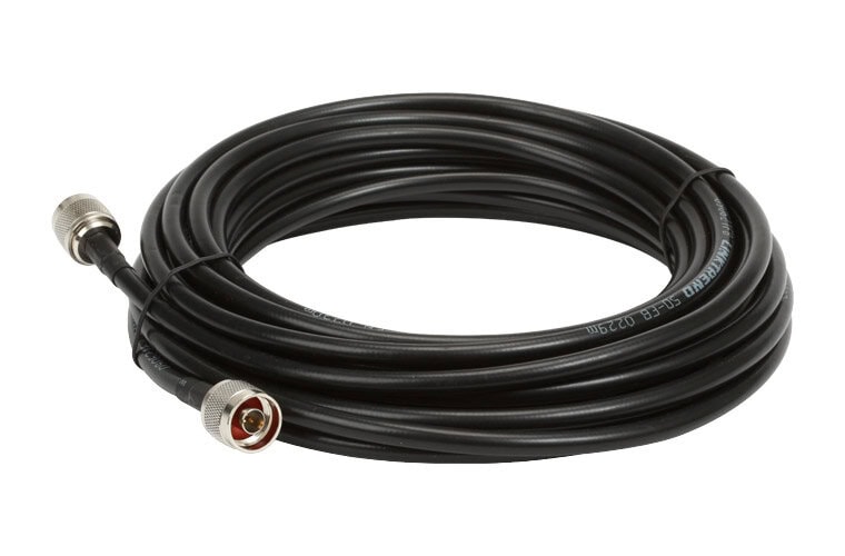
- N-Type: Sturdy connectors used for applications requiring durability and weather resistance, such as outdoor antennas.
- Reverse Polarity (RP) Variants: These include RP-SMA and RP-TNC, frequently used in wireless networking gear to meet regulatory requirements.
Understanding Connector Genders
Unlike household plumbing, the “gender” in antenna connectors doesn’t always refer to the outer threads. Instead, it’s all about what’s inside:
Standard Connectors:
Male: Features a center pin (the “plug”) and typically threads on the outside.
Female: Contains a center socket (the “jack”) and has internal threads.
Reverse Polarity (RP) Connectors:
The names can be deceiving. RP connectors swap the internal pin and socket arrangement, so an RP-male has a body like a male connector but contains a socket, while an RP-female has a male-like body but with a center pin.
This reversal helps prevent accidental connections between incompatible devices and is mandated by certain wireless standards.
Quick Reference
- SMA Male: Center pin present.
- SMA Female: Center socket.
- RP-SMA Male: Center socket (despite “male” threads).
- RP-SMA Female: Center pin (despite “female” threads).
- The same logic applies to TNC and N-type connectors with RP versions.

Always double-check both the body and the internal contact of your connector, especially when dealing with RP types, as appearances can be misleading.
With a solid understanding of connector types and gender, you can confidently select the proper cable for your antenna setup, avoiding guesswork and ensuring a reliable connection.
Key Differences Between Standard and Reverse Polarity Connectors
When it comes to antenna cables, understanding the difference between standard and reverse polarity (RP) connectors is essential, especially since the two are not interchangeable.
Standard Connectors:
- In standard coaxial connectors like SMA or TNC, the gender designations are straightforward:
- “Male” connectors have a center pin.
- “Female” connectors have a center socket.
- For example, an SMA-male has a protruding pin, while an SMA-female presents a recessed socket.
Reverse Polarity (RP) Connectors:
- RP connectors were introduced primarily to comply with certain FCC regulations and to prevent accidental mismatching between consumer and professional equipment.
- The key twist is that the center contacts are swapped:
- RP-male connectors look like a male by body type, but instead of a pin, you’ll find a socket.
- RP-female connectors appear female by housing, but have a center pin rather than a socket.
- For example, an RP-SMA male has the outer threads typical of a male connector but features a socket inside, while an RP-SMA female retains the barrel design but comes with a pin.
Why Does This Matter?
- Standard and RP connectors cannot connect with each other, as their center contacts will not align. Forcing a connection can damage both connectors and reduce signal integrity.
- It’s important to match connector types precisely when assembling your system, especially if you’re connecting equipment from brands like TP-Link, Cisco, or Ubiquiti, which may use different types for compatibility and regulatory purposes.
By recognizing these distinctions, you’ll ensure you select the right connector for your application, avoid common setup frustrations, and maintain optimal signal quality.
How Do Reverse Polarity and Reverse Gender Connectors Satisfy Regulatory Requirements?
To comply with regulations like FCC Regulation 15, many antenna cables use reverse polarity (RP) or reverse gender connectors. But what does this actually mean? In essence, these connector types have their internal contact pins swapped from their traditional male and female roles, despite the external housing looking familiar.
For example, a reverse polarity connector might have a plug that externally resembles a standard male connector, but inside, it contains the contact you’d typically find in a female connector. This switch isn’t just a quirky engineering decision—it serves a specific regulatory purpose.
By making it impossible to directly connect RP connectors with standard coaxial connectors from devices such as Linksys or Netgear wireless routers, manufacturers help ensure that only approved antennas can be used. This reduces the risk of unintentional interference or violations of equipment certification, since end-users can’t simply attach higher-gain antennas without using very specific adapters or hardware.
Attempting to force incompatible connectors together can actually damage the connectors, so it’s always best to confirm your cable’s compatibility before making any connections. This small but clever design tweak plays a big role in maintaining signal integrity and staying within regulatory guidelines.
How to Identify the Gender of Threaded RF Connectors
Determining the gender of threaded RF connectors—such as SMA, TNC, N, RP-SMA, and RP-TNC—can be surprisingly tricky. Unlike most connectors, where gender is based on the outer threads, in RF connectors the designation actually refers to the presence of a pin or a socket inside the connector.
- Male connectors typically have a central pin.
- Female connectors have a central socket.
This holds true for standard versions:
- For example, an SMA-male will have a pin, while an SMA-female will have a socket.
- Likewise, TNC-male = pin, TNC-female = socket.
The “Reverse Polarity” (RP) Twist
Some connectors—like RP-SMA and RP-TNC—introduce another layer of complexity with “reverse polarity.” Here, the outward appearance (the threads) stays the same, but the center pin and socket are swapped:
- An RP-SMA-female will have a pin (unlike a standard female).
- An RP-SMA-male will have a socket (unlike a standard male).
This design is intentional and is used to comply with regulatory requirements, such as those set by the FCC. It also means that reverse polarity connectors do not mate with standard connectors of the same thread type—mixing them can cause damage.
Quick Reference: Standard vs. RP Connectors
- Standard: Male = pin; Female = socket
- Reverse Polarity (RP): Male = socket; Female = pin
When identifying the gender of a threaded RF connector, always look inside to check for a pin or socket, rather than relying on external threading. For “RP” connectors, remember the pin and socket roles are reversed compared to standard connectors with the same threads.
Now, let’s take a closer look at how these connectors interact with the antenna cable itself.
How Does the Antenna Cable Work?
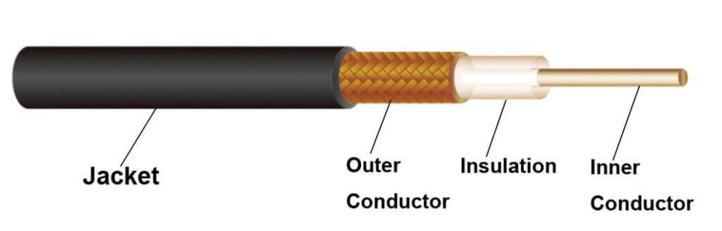
The antenna cable typically consists of a central conductor, usually made of copper or aluminum, surrounded by a dielectric insulator material, such as foam or plastic, which helps to maintain the integrity of the signal by preventing interference and signal loss. Surrounding the dielectric material is a metallic shield, usually made of braided copper or aluminum, which acts as a barrier against external electromagnetic interference.
When a radio frequency signal is transmitted through the antenna cable, it travels along the central conductor, with the dielectric material helping to maintain the signal’s strength and integrity. The metallic shield surrounding the cable helps to protect the signal from external interference, such as electromagnetic radiation from nearby electronic devices or power lines.
Overall, the antenna cable works by providing a pathway for radio frequency signals to travel from the antenna to the receiver or transmitter with minimal loss and interference, ensuring that the signal remains strong and clear. Proper installation and maintenance of the antenna cable are crucial for optimal signal transmission and reception.
Understanding Signal Loss in Antenna Cables
Antenna cables are not immune to signal degradation—some of the signal power entering the cable is inevitably lost as it travels, a phenomenon known as attenuation. This loss is measured in decibels per unit length at a given frequency, and it increases proportionally with the length of the cable: for example, the attenuation at 10 feet is ten times greater than at one foot.
The quality and construction of the cable play a major role in minimizing this loss. Modern low-loss, double-shielded coaxial cables—such as LMR-100, LMR-200, and LMR-400—are engineered to offer better shielding and lower attenuation compared to older, standard RG cables like RG-174, RG-178, or RG-58. Low-loss cables typically use a solid center conductor (rather than stranded wire), which further helps to reduce signal loss, and are suitable for both indoor and outdoor applications.
Key points to reduce signal loss:
- Choose the shortest cable possible for your setup. The shorter the cable, the less signal loss you’ll experience.
- Select the right cable type: Thicker cables (such as LMR-400) have lower attenuation over long distances, while thinner cables (like LMR-100) are better for short runs.
- Consider double-shielded cables for environments with high electromagnetic interference.
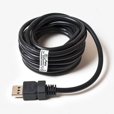
For specialized applications, such as WLAN, cellular, or ISM bands, using a high-quality, appropriately rated coaxial cable is essential. If you need to run cables over longer distances, consider alternatives like Ethernet cables with Power over Ethernet (PoE) for wireless devices, or use USB extension cables to keep your device as close to the antenna as possible.
By understanding the structure of antenna cables and the factors that contribute to signal loss, you can make informed choices to ensure your devices receive the clearest, strongest signal possible.
What Are the Recommended Cable Types and Lengths to Minimize Signal Loss?
When it comes to antenna installations, choosing the right cable type and length is key to maintaining signal quality. The primary goal is to minimize attenuation, or signal loss, which naturally occurs as radio frequency power travels through the cable.
Selecting the Right Cable Type
Antenna cables fall into several categories, but not all are created equal in terms of performance:
- Low-loss coaxial cables like LMR-100, LMR-200, and LMR-400 are widely recognized for their superior shielding and lower attenuation per meter compared to traditional RG-Style cables (such as RG-58 or RG-174). The main difference lies in the construction—low-loss cables often have a solid center conductor and double shielding, both of which help preserve signal integrity over distance.
- For short cable runs (under 2 meters), cables equivalent to LMR-100 or higher provide excellent performance with minimal signal loss.
- For medium lengths (between 2 and 9 meters), step up to cables similar in quality to LMR-200 to keep attenuation low.
- For longer distances (9 meters or more), using robust options like LMR-400 is recommended, as their design significantly reduces signal degradation, especially at higher frequencies.
Keep Cables as Short as Possible
No matter how high-quality the cable, signal loss adds up with every additional foot. It’s always best to use the shortest cable that your setup allows. In scenarios where the antenna must be far from the device, consider repositioning equipment or running Ethernet cable with Power over Ethernet (PoE), which can preserve power and data over much longer distances compared to coaxial cables.
Practical Tips to Minimize Signal Loss
- Whenever feasible, move your device closer to the antenna to use a shorter cable run.
- For USB WiFi adapters, consider using USB extension cables to place the adapter in a clear line of sight or even outdoors in a weatherproof enclosure, instead of running long antenna cable runs.
- For access points or bridges, running Ethernet with PoE is often more efficient, allowing for cable runs up to 175 feet (and even longer with higher-voltage PoE).
By carefully choosing your cable type and keeping lengths as short as practical, you’ll ensure your antenna installation delivers the strongest, clearest signal possible.
How Does Low-Loss Coaxial Cable Construction Compare to Standard RG Cables?
Not all antenna cables are created equal. The design and materials used in a cable’s construction play a significant role in how well it transmits signals—and how much interference or loss occurs along the way.
Low-loss coaxial cables stand apart from standard RG (Radio Guide) cables in several key ways:
Shielding Layers: While traditional RG cables typically feature a single layer of shielding, low-loss coaxial cables are engineered with multiple shielding layers—often double or even more. These additional barriers drastically reduce electromagnetic interference, resulting in a cleaner, stronger signal.
Conductor Design: Low-loss cables usually employ a solid center conductor, most often made from copper or aluminum. This solid core helps maintain lower signal attenuation (less loss over distance) compared to the stranded conductors sometimes used in standard RG cables.
Cable Series and Sizes: Low-loss coaxial cables are also available in a range of sizes commonly referred to as “100-series,” “200-series,” and “400-series,” which indicate the diameter of the cable. The thicker the cable (such as the 400-series at 0.4 inches in diameter), the lower the attenuation over longer runs—making them ideal when you need to cover significant distances without degrading your signal.
In summary, the superior shielding and solid core of low-loss coaxial cables make them the preferred choice wherever minimizing signal loss and interference is critical. Proper selection of cable type ensures you get the most out of your antenna system, especially in environments dense with electronic devices or over longer cable stretches.
Why Is Double-Shielded Coaxial Cable Preferred for Antenna Use?
When selecting antenna cables, the choice between single-shielded and double-shielded coaxial cable is more than just a technicality—it can have a direct impact on your signal quality and overall connection reliability.
Double-shielded coaxial cable is engineered with two distinct layers of shielding, typically made from materials like braided copper or aluminum foil. This dual-layer design offers several key advantages over single-shielded options (like standard RG cables):
Enhanced Protection Against Interference: The extra shield acts as an added barrier, significantly reducing electromagnetic interference (EMI) from nearby devices, power lines, or even Wi-Fi routers. This means your cable can better defend itself in electrically noisy environments, ensuring your signal stays crisp and clear.
Reduced Signal Loss: Double-shielding plays a critical role in minimizing signal attenuation. This is especially important for longer cable runs, where signal loss can become a noticeable issue with single-shielded cables. The improved shielding helps preserve signal strength from the antenna all the way to your device.
Improved Consistency: Double-shielded cables often use a solid center conductor rather than a stranded one. Solid conductors are optimal for low-frequency signal transmission and help achieve lower attenuation rates, which translates to more reliable performance.
For these reasons, upgrading to double-shielded coaxial cable is highly recommended—especially if you’re aiming for the best possible reception, minimal dropouts, or are dealing with a challenging installation environment.
Using quality double-shielded coaxial cables is a straightforward way to maximize your antenna’s performance and safeguard against unwanted interference, making them the preferred choice for both home and professional installations.
Operational Temperature Range and Key Physical Properties
When selecting an antenna cable, knowing its operational limits and core properties helps ensure reliable performance—especially in demanding environments. Here’s what you should keep in mind:
Temperature Range
Most 100-series coaxial antenna cables are built to function in varied conditions, typically operating smoothly anywhere from -4°F to +176°F (-20°C to +80°C). This broad range means your cable won’t bat an eye at everyday temperature swings, whether you’re installing it in a summer attic or a frosty basement.
Core Electrical and Physical Specifications
While antenna cables share a similar design, key specs can vary by type. Notable properties include:
- Capacitance: Ranges from about 81 to 100 picofarads per meter (pF/m), affecting how signals are transmitted along the cable.
- Impedance: Generally standardized at 50 ohms (Ω), with a tolerance of ±2Ω. This is crucial for matching your cable to the connected devices, minimizing signal reflection.
- Velocity Ratio: Indicates signal propagation speed relative to light, typically between 66% and 86%. Higher ratios often translate to more efficient signal transmission.
- Bend Radius: Minimum bend radius varies (commonly 15mm to 25mm), guiding safe installation without risking internal damage.
- Maximum Voltage and Frequency: Many antenna cables handle up to 1500 volts (V) and can support frequencies up to 3000 megahertz (MHz), making them suitable for a range of applications from home WiFi to professional broadcast setups.
Understanding these specifications will help you choose the right cable for your needs, ensuring optimal signal strength, minimal loss, and durability in any environment.
Best Practices for Waterproofing and Weatherproofing Antenna Cable Connectors
When it comes to safeguarding your antenna setup from the elements, choosing the right connectors and taking proper precautions are key to long-lasting performance.
Connector Material Matters
For outdoor installations, connectors with nickel plating—such as N-type connectors—offer excellent resistance to corrosion and weathering. They’re specifically engineered to stand up to years of rain, humidity, and temperature swings without succumbing to rust or signal degradation.
On the other hand, gold-plated brass connectors, including the commonly seen SMA and RP-SMA types, are more suitable for indoor use. While they offer superior conductivity, they don’t fare as well in harsh outdoor environments over time. Extended exposure to moisture and environmental stress can eventually cause these connectors to deteriorate if left unprotected.
Protective Measures for Outdoor Installations
If your setup requires SMA or RP-SMA connectors outdoors—perhaps due to device compatibility or specific installation needs—it’s important to add an extra layer of defense. Here are a few practical steps:
- Weatherproof Sealing: Use a self-amalgamating tape, such as CoaxSeal or 3M Scotch Self-Fusing Silicone Tape, to thoroughly wrap and seal all outdoor connection points. Focus especially on gold-plated brass connectors, but it’s also wise to apply protection to nickel-plated connectors for ultimate reliability.
- Routine Checks: Inspect your connectors periodically to ensure seals remain intact and dry. Replace or reapply the weatherproof tape as necessary, particularly after storms or seasonal changes.
- Proper Installation: Ensure connectors are tightly fastened and positioned away from direct water flow or pooling whenever possible.
By using high-quality materials and weatherproofing techniques, you can significantly extend the lifespan of your antenna cables and maintain optimal signal quality.
What Factors Influence Signal Loss in Different Types of Coaxial Antenna Cables?
Not all antenna cables are created equal, and their effectiveness largely hinges on one thing: signal loss, also known as attenuation. Signal loss is a natural phenomenon that occurs as radio frequency (RF) signals travel through a coaxial cable. The longer the cable, the more opportunity for the signal to degrade before reaching your device. But cable length isn’t the only factor at play—cable type and construction matter just as much.
Key Factors Affecting Signal Loss
1. Cable Diameter and Construction:
Coaxial cables come in various “series”—commonly referred to by numbers like 100-series, 200-series, and 400-series, or familiar codes like RG-174, RG-178, and RG-58.
- Thicker cables (such as 400-series) generally have lower signal loss per foot compared to thinner types (like 100-series or RG-174).
- Quality cables typically have double shielding (two layers of protective metal around the core), which helps reduce interference, while more basic cables may only use a single shield, making them more prone to signal loss from external sources.
2. Shielding Quality:
Double-shielded cables—like many LMR-series or the higher-end 100/200/400-series types—offer superior protection against electromagnetic interference (EMI) compared to single-shielded RG-series cables. Better shielding translates into less unwanted noise and stronger signal integrity, especially in environments with lots of electronic devices.
3. Conductor Material:
A solid copper conductor carries RF signals with less resistance (and therefore less attenuation) than copper-clad steel or stranded copper, which might be found in some lower-cost RG cables.
4. Frequency of Operation:
Signal loss increases with frequency. That means attenuation is higher at frequencies used in WiFi or cellular applications (measured in MHz or GHz) than at lower frequencies like those for FM radio. For example, a 100-series cable will lose more signal per foot at 2.4 GHz (WiFi range) than at 900 MHz.
5. Length of the Cable:
Signal loss compounds with length. If possible, always use the shortest cable necessary to minimize attenuation. Doubling the length of the cable doubles the loss.
Comparing Common Coaxial Cable Types
- 100-Series (e.g., LMR-100): Slim, flexible, and great for short runs—typically less than 2 meters. Attenuation rises notably at high frequencies, but double shielding and solid copper conductors help maintain signal quality for compact installations.
- 200-Series (e.g., LMR-200): A bit thicker, offering lower loss and suitable for medium cable runs. Its solid copper core and double shielding make it a practical choice for both indoor and outdoor setups.
- 400-Series (e.g., LMR-400): Considerably thicker and heavier, but best for long runs or demanding applications where keeping signal loss to a minimum is critical.
- RG-174, RG-178, RG-58: These classic RG-style cables are thinner and often single-shielded. While flexible and easy to route, they’re more prone to interference and higher attenuation, especially over longer distances or higher frequencies.
Practical Tips for Minimizing Signal Loss
- Choose the right cable for your frequency and cable run length—thicker and higher-quality cables for longer distances or higher-frequency applications.
- Keep it short: Always use the shortest reasonable length between your device and antenna.
- Prioritize shielding and connectors: Opt for cables with double shielding and high-quality, soldered connectors for reliable, interference-resistant performance.
By understanding and selecting your antenna cable wisely, you ensure stronger, clearer signals across your setup—keeping your TVs sharp, your WiFi fast, and your radios humming along, whether in a bustling office or a cozy living room.
What Is an Antenna Cable Used For?
Antenna cables are used to transmit radio frequency signals between an antenna and a device, such as a television, radio, or router. They are typically used to improve the reception and transmission of signals, allowing for better quality audio and video. Antenna cables are commonly used in homes, offices, and vehicles to connect devices to external antennas for improved signal strength and performance.
In summary, antenna cables are used for:
1. Connecting televisions to rooftop antennas for better reception of TV signals.
2. Linking radios with external antennas for improved communication range and clarity.
3. Enhancing the performance of routers and modems by connecting them to external antennas for better Wi-Fi signal strength.
4. Extending the reach of cellular signal boosters by connecting them to external antennas for improved cell phone reception.
5. Connecting devices like walkie-talkies and ham radios to external antennas for better communication in remote or challenging environments.
What Is an Antenna Cable vs Coaxial Cable?
Antenna cables are specifically designed for connecting antennas to electronic devices, such as TVs, radios, or routers, to receive signals from broadcasting stations. They are typically coaxial cables, which consist of a center conductor surrounded by an insulating layer, a conductive shield, and an outer insulating jacket. The shield helps to minimize interference and signal loss, making them ideal for transmitting high-frequency signals over long distances.
Coaxial cables, on the other hand, are a type of electrical cable that consists of an inner conductor, insulating material, a conductive shield, and an outer insulating jacket. They are commonly used in a variety of applications, including telecommunications, computer networks, and audio/video systems. While some coaxial cables may be used as antenna cables, not all coaxial cables are specifically designed for this purpose.
In summary, antenna cables are a specific type of coaxial cable designed for connecting antennas to electronic devices, while coaxial cables are a more general type of cable used in a variety of applications. The key difference lies in their intended use and the specific requirements they meet for transmitting signals effectively.
What is the difference between coaxial cable and regular cable?
Coaxial cable consists of a central conductor surrounded by an insulating layer, a metallic shield, and an outer insulating layer. This design helps to minimize signal interference and maintain signal strength over longer distances. In contrast, regular cable (twisted pair cable) consists of two conductors twisted together, which can be more susceptible to interference and signal loss.
Additionally, coaxial cables are typically used for higher frequency applications, such as cable television and internet, while twisted pair cables are commonly used for lower frequency applications, such as telephone lines. Coaxial cables also have higher bandwidth capabilities compared to twisted pair cables, allowing for faster data transmission speeds.
Overall, the main difference between coaxial cable and regular cable is their design and intended use, with coaxial cables being better suited for high-frequency applications requiring longer cable lengths and better signal quality.
Specifications and Performance: 100-Series, 200-Series, and 400-Series Coaxial Cables
Coaxial cables come in several varieties, each with distinct specifications and levels of signal loss—referred to as attenuation. It’s helpful to understand these differences when choosing a cable for your antenna setup.
100-Series Coaxial Cable
This slim cable is often chosen for short connections, typically under 7 feet. The 100-series features a bare copper core with multiple layers of insulation and shielding to minimize interference.
Key properties:
- Impedance: 50 ohms
- Capacitance: Around 100 pF/m
- Max frequency: Up to 3,000 MHz
- Temperature range: -20°C to +80°C
Attenuation (signal loss) increases as frequency goes up:
- At 900 MHz: About 0.23 dB per foot
- At 2.4 GHz: About 0.39 dB per foot
- At 5 GHz: About 0.64 dB per foot
The takeaway? The 100-series is ideal for relatively short runs where minimal signal loss is acceptable and cable flexibility is important.
200-Series Coaxial Cable
If you need a bit more distance or lower signal loss, 200-series cables offer a solid middle ground. They feature a larger diameter conductor, foam polyethylene insulation, and improved shielding, which further reduces attenuation.
Key properties:
- Impedance: 50 ohms
- Capacitance: About 81 pF/m
- Max frequency: Up to 3,000 MHz
- Temperature range: -20°C to +80°C
Notable attenuation rates:
- At 200 MHz: ~16 dB per 100 meters
- At 900 MHz: ~33 dB per 100 meters
- At 2.5 GHz: ~56 dB per 100 meters
This makes the 200-series a good choice for medium-length cable runs where signal integrity is a priority.
400-Series Coaxial Cable
For installations where the cable stretch gets serious—think long runs between outdoor antennas and indoor equipment—400-series coax is the heavyweight champion. The thicker conductor and robust insulation dramatically lower signal loss, even at high frequencies.
Key properties:
- Impedance: 50 ohms
- High power handling capacity
- Suitable for frequencies up to 8,000 MHz (8 GHz)
- Lower attenuation compared to thinner cables
Sample attenuation values per 100 feet:
- At 900 MHz: 3.9 dB
- At 2.5 GHz: 6.8 dB
- At 5.8 GHz: 10.8 dB
To sum up, when choosing a coaxial cable, consider both the length required and the frequency range you’ll be working with. Using a thicker cable like the 400-series can ensure your signal makes it to its destination with as little loss as possible.
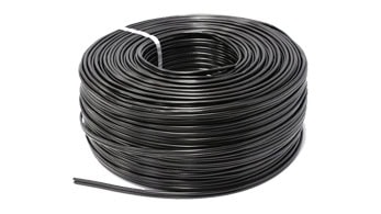
What Does an Antenna Cable Look Like?
The cable itself is typically made of copper or aluminum, with a protective outer layer of insulation to prevent interference and damage. Antenna cables come in various lengths and thicknesses, depending on the specific application and signal strength needed. Overall, antenna cables are designed to efficiently transmit radio frequency signals between devices and antennas for optimal performance.
How Reverse Polarity (RP) Affects Connector Gender and Compatibility
When dealing with connectors like N, SMA, TNC, and their reverse polarity counterparts (RP-SMA, RP-TNC), it’s easy to be thrown off by how gender is determined. Typically, the gender of these connectors is based not on the external threads, but on the inner center pin or socket.
Here’s where reverse polarity (RP) adds a twist:
- For standard connectors (such as SMA or TNC), a “male” connector has a center pin, and a “female” connector has a center socket—no surprises there.
- RP versions swap the expected pin-and-socket configuration: an RP-male connector has a center socket instead of a pin, while an RP-female connector has a center pin instead of a socket.
- This can be confusing because the external appearance (threads or body) might still resemble the standard version, but the center contact is reversed.
Why the change?
Reverse polarity connectors, like RP-SMA and RP-TNC, were developed primarily to comply with regulations (such as FCC rules), to help prevent accidental connections between devices—particularly with wireless equipment. This is achieved by switching the dielectric and contact so they won’t physically connect with standard connectors.
Compatibility matters:
- RP connectors are not directly compatible with their standard counterparts, despite looking deceptively similar. For instance, an RP-SMA male will not mate correctly with a regular SMA female, and vice versa.
- Attempting to force a connection between RP and standard connectors can damage the connectors, so it’s best to double-check the pin configuration before connecting.
In short, reverse polarity affects both the internal structure and the compatibility of connectors. Always look carefully at the pin or socket—don’t rely solely on the outer threads or the connector’s “male” or “female” label—to ensure a proper match.
What Is CoaxSeal and How Does It Protect Antenna Cable Connectors Outdoors?
When antenna cables and connectors are installed outdoors, they’re exposed to rain, humidity, dust, and fluctuating temperatures—all of which can lead to corrosion or signal loss over time. This is especially true for connectors with gold-plated brass, such as SMA and RP-SMA types, which are commonly used for connecting antennas to routers, radios, and other wireless equipment.
CoaxSeal is a pliable sealing tape designed specifically for weatherproofing cable connections. By wrapping CoaxSeal around the connectors, you create a moisture-resistant barrier that protects against the elements, helping to prolong the life and performance of your antenna system.
How to Use CoaxSeal for Outdoor Installations
- Wrap CoaxSeal snugly around all exposed connectors, paying close attention to areas where cables meet antennas or adapters.
- For installations where durability is especially important—such as long-term outdoor setups—it’s a good idea to also protect larger connectors like nickel-plated N-type adapters.
- The cost is minimal, and the peace of mind it offers in terms of safeguarding your equipment can be well worth the small investment.
Properly sealing your connectors not only reduces interference but also helps maintain strong signal quality, even in demanding outdoor environments.
Coaxial cable advantages and disadvantages
Advantages of coaxial cable:
- 1. High bandwidth capacity: Coaxial cables can support a large amount of data transmission due to their high bandwidth capacity.
- 2. Better signal quality: Coaxial cables provide better signal quality compared to other types of cables, resulting in less interference and better overall performance.
- 3. Long distance transmission: Coaxial cables can transmit data over long distances without loss of signal quality.
- 4. Durability: Coaxial cables are more durable and resistant to interference and damage compared to other types of cables.
- 5. Easy to install: Coaxial cables are easy to install and can be used for various applications such as internet, cable TV, and security systems.
Disadvantages of coaxial cable:
- 1. Limited flexibility: Coaxial cables are less flexible compared to other types of cables, making them difficult to bend or twist in tight spaces.
- 2. Cost: Coaxial cables can be more expensive than other types of cables, especially for higher quality cables with better performance.
- 3. Size and weight: Coaxial cables are larger and heavier than other types of cables, which can make installation more challenging.
- 4. Susceptible to interference: While coaxial cables provide better signal quality, they can still be susceptible to interference from external sources such as electromagnetic interference.
- 5. Limited compatibility: Coaxial cables may not be compatible with all devices or systems, limiting their use in certain applications.
Typical Attenuation Rates for Common Coaxial Cable Types
Attenuation, or signal loss, varies between coaxial cable types and depends on frequency. Here’s a breakdown of some widely used coaxial cables and their general attenuation rates at different frequencies:
100-Series Coaxial Cable:
Often used for very short antenna runs, this cable features double shielding to minimize signal interference. Its attenuation rates per foot are approximately:
- At 900 MHz: 0.23 dB
- At 2.4 GHz: 0.39 dB
- At 3.4 GHz: 0.47 dB
- At 5.8 GHz: 0.64 dB
200-Series Coaxial Cable:
With a larger core and improved insulation, the 200-series offers lower signal loss over distance. Typical attenuation rates per 100 meters include:
- At 200 MHz: 16 dB
- At 400 MHz: 24 dB
- At 900 MHz: 33 dB
- At 1500 MHz: 43 dB
400-Series Coaxial Cable:
Known for its durability and low loss, the 400-series is great for longer runs. Example attenuation per 100 feet:
- At 900 MHz: 3.9 dB
- At 2.4 GHz: 6.6 dB
- At 5.8 GHz: 10.8 dB
RG-174:
Common for short connections and patch cables, but higher loss than thicker cables:
- At 900 MHz: 0.31 dB/ft
- At 2.4 GHz: 0.60 dB/ft
- At 5.8 GHz: 1.11 dB/ft
RG-178:
A thinner alternative with clear insulation, but also higher loss rates:
- At 900 MHz: 0.55 dB/ft
- At 2.4 GHz: 0.89 dB/ft
- At 5.8 GHz: 1.38 dB/ft
RG-58:
A popular general-purpose coax, often used for radio and networking:
- At 900 MHz: 0.14 dB/ft
- At 2.4 GHz: 0.26 dB/ft
- At 5.8 GHz: 0.48 dB/ft
As a rule of thumb, the higher the frequency and the thinner the cable, the greater the attenuation. When choosing coaxial cable for your setup, consider both the required length and the highest frequency in use to minimize signal loss and ensure reliable performance.
Risks of Mismatching Reverse Polarity and Standard Coaxial Connectors
Attempting to connect reverse polarity (RP) connectors with standard coaxial connectors can lead to several issues. While RP connectors might appear similar at first glance, their internal design—specifically the arrangement of the pins and sockets—is different. This intentional difference is meant to prevent accidental or unauthorized connections, as required by regulations.
If you try to force an RP connector to mate with a standard connector, you risk damaging the delicate internal contacts or the dielectric. This not only compromises the connector itself but also affects overall signal quality and could even render the connectors unusable. In most cases, the connectors simply won’t fit together properly, but persistent attempts can result in permanent mechanical damage to both ends.
For best results and to ensure proper function and safety, always match connector types exactly when setting up coaxial cable connections.
Solutions for Long Cable Runs: USB WiFi Adapters and Power Over Ethernet (PoE)
When dealing with long cable runs, signal loss can become a significant concern. Fortunately, there are a couple of practical ways to tackle this issue, especially when using USB WiFi adapters and devices powered through Ethernet.
Positioning USB WiFi Adapters: To improve performance and reduce signal degradation, you can use USB extension cables to place your WiFi adapter in a direct line of sight to the access point. For even better reception, consider mounting the adapter outdoors (such as on a roof) inside a weatherproof enclosure. This approach brings the adapter closer to the signal source, minimizing barriers and improving signal quality over long distances.
Utilizing Power Over Ethernet (PoE): For devices like wireless access points or network bridges, PoE offers an effective way to power and connect your device using a single Ethernet cable. Standard Ethernet cables can transmit both data and power for distances up to approximately 175 feet. If you need to run cables even farther, opting for higher-voltage PoE solutions (such as 48V systems) helps compensate for voltage drop over long runs. And if your device requires a specific voltage, you can always use a step-down voltage adapter at the end of the line.
These strategies help maintain strong, reliable connections by reducing the impact of distance and signal loss in your setup.
Is Antenna Cable and Coaxial Cable the Same?
Antenna cable is a type of coaxial cable that is specifically designed for transmitting radio frequency signals between antennas and electronic devices. Coaxial cable, on the other hand, is a more general term for any cable that consists of an inner conductor surrounded by a tubular insulating layer, which is then surrounded by a tubular conducting shield.
In summary, all antenna cables are coaxial cables, but not all coaxial cables are necessarily meant for use with antennas. The terms are often used interchangeably, but it’s important to understand the specific application and intended use of the cable in question.
Can I Use the Existing Coax Cable for the Antenna?
Yes, you can use the existing coax cable for the antenna as long as it is in good condition and properly connected. Make sure the cable is compatible with the antenna and that it is securely connected to both the antenna and the receiver. If the cable is old or damaged, it may need to be replaced to ensure optimal signal quality.
It is important to note that using an existing coax cable may affect the signal quality and performance of the antenna. If you experience poor reception or interference, it may be necessary to upgrade to a higher quality coax cable specifically designed for antennas.
In conclusion, antenna cables are essential components that enable seamless communication and connectivity in our interconnected world. By understanding the different types of antenna cables, their uses, and technical aspects, you can optimize your devices for peak performance. Whether you are setting up a home network, installing a satellite dish, or connecting to a cellular tower, choosing the right antenna cable is crucial for ensuring strong signal strength and reliable communication. Dive into the realm of antenna cables to enhance your tech experience and stay connected in today’s digital age.
